🔧 Huanghe Cable | Products & Technical Guides | Power Cable Ampacity | IEC 60287
⏱️ Estimated reading time: 18 minutes
Key Takeaways for Electrical Engineers & Procurement Teams
Power cable ampacity (current-carrying capacity) is the maximum continuous electric current a cable can carry under specified installation and environmental conditions without exceeding its insulation thermal limit. Under IEC 60287, ampacity is calculated based on conductor resistance, ambient environment, and dielectric or electromagnetic losses.
When engineers compare power cable quotations, current rating is often one of the first numbers they check. A datasheet may show an ampacity for a particular conductor size, but that number should never be treated as a universal value for every installation.
A 630 mm² XLPE cable, for example, does not have one fixed ampacity that applies to every project. The permissible current depends on how the cable is constructed and installed, how heat moves away from the cable, how many circuits are grouped together and which calculation assumptions are being used.
This is why IEC 60287 is important for cable engineering. The standard provides calculation methods for current rating and losses under steady-state conditions. For procurement teams, understanding the main inputs helps prevent technically different cable offers from being compared only by the ampacity number printed on a quotation.
Table of Contents
The conductor cross-section is one of the most obvious factors affecting current-carrying capacity. In general, a larger conductor provides a greater area for current flow and can reduce electrical resistance.
However, cross-section alone does not define ampacity. Copper and aluminum conductors have different electrical and thermal properties, so two cables with the same nominal cross-sectional area should not automatically be expected to have identical current ratings.
| Conductor Parameter | Effect on Current Rating |
|---|---|
| Cross-sectional area | Affects conductor resistance and heat generation. |
| Copper conductor | Has lower electrical resistivity than aluminum and therefore different loss characteristics. |
| Aluminum conductor | Requires its own resistance and thermal parameters in the cable calculation. |
| Conductor construction | Stranding and actual conductor design affect resistance and physical dimensions. |
This is one reason why a procurement specification should state both the conductor material and cross-section, rather than simply asking for a cable capable of carrying a particular current.
For Huanghe Cable LV and MV power cable quotations, conductor material can be specified as part of the cable construction so that the technical offer can be evaluated against the project requirement.
Conductor resistance is a major source of heat in a loaded cable. As current flows through the conductor, electrical losses occur, and those losses contribute to the cable’s temperature rise.
In AC power systems, conductor losses are calculated using the effective AC resistance (RAC) at the maximum operating temperature:
P = I² × RAC
Where P is conductor resistive loss per unit length, I is current, and RAC is the alternating-current resistance. Unlike direct-current resistance (RDC), RAC includes resistance increases caused by skin effect (ys) and proximity effect (yp):
RAC = RDC (1 + ys + yp)
Ignoring these high-frequency and electromagnetic effects—especially in large conductor cross-sections (e.g., ≥ 400 mm²)—will result in an overestimation of cable ampacity.
IEC 60287 Connection
IEC 60287-1-1:2023 provides equations for current rating and losses under steady-state operation. The calculation deliberately leaves certain parameters open because cable construction, surrounding conditions and agreed design parameters can vary between projects.
This means that two suppliers can quote the same conductor size but arrive at different ampacity figures if their calculation assumptions are different. The solution is not necessarily to choose the higher number; it is to compare the calculation basis and installation assumptions.
The physical installation has a direct effect on how efficiently a cable can release heat into its surroundings.
IEC 60287 specifies calculation methods for continuous current ratings and losses of power cables under 100% load factor steady-state operation. While IEC 60287-1-1 focuses on conductor resistance, dielectric losses, and metallic sheath/armour loss equations, environmental thermal resistance conditions (such as directly buried cables, ducts, troughs, and cables in free air) are calculated using formulas in IEC 60287-2-1. (Note: For transient or cyclic loading calculations, engineers should refer to IEC 60853).
These conditions are not thermally equivalent.
| Installation Method | Main Thermal Consideration |
|---|---|
| Direct buried | Soil thermal properties, burial conditions, depth and surrounding cables affect heat dissipation. |
| Duct | Heat transfer through the cable, duct and surrounding medium must be considered. |
| Cable tray / air | Ambient temperature, ventilation and cable arrangement affect the thermal environment. |
| Steel pipe | The surrounding metallic installation can affect thermal and electromagnetic behavior. |
This is why an ampacity printed on a manufacturer’s catalogue should always be read together with its installation condition.
If a project changes from direct burial to duct installation after cable selection, the original current-rating calculation may need to be reviewed.
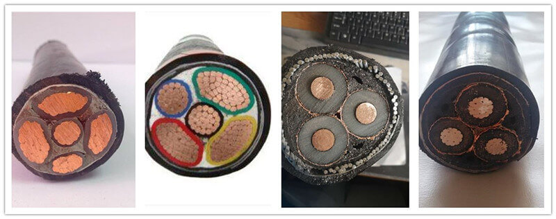
Heat dissipation depends heavily on the environment around the cable. For cables installed in air, the ambient temperature is an important input. For buried cables, the thermal properties of the surrounding soil become particularly important.
Soil thermal resistivity describes how readily heat moves through the soil. A higher thermal resistivity means more difficulty in transferring heat away from the cable, all else being equal.
Soil thermal resistivity is expressed in K·m/W (Kelvin meters per Watt). Standard calculations often assume a default value (e.g., 1.0 K·m/W or 1.5 K·m/W), but actual soil conditions vary significantly along a cable route. Furthermore, under heavy continuous thermal load, heat driven from the cable can cause moisture to migrate away from the trench (soil drying out). This localized drying dramatically increases thermal resistivity (sometimes exceeding 2.5–3.0 K·m/W), risking severe thermal runaway and premature insulation breakdown.
This is particularly relevant in large underground power cable projects. Soil conditions can vary along a route, and the design assumptions should be consistent with the engineering basis used for the project.
| Environmental Input | Why It Matters |
|---|---|
| Ambient air temperature | Higher surrounding temperature reduces the available thermal margin. |
| Soil thermal resistivity | Controls the ability of buried cable systems to transfer heat into the surrounding soil. |
| Soil condition | Moisture and drying conditions can influence effective thermal behavior. |
| Installation depth | Changes the thermal path and may affect the calculation assumptions. |
For projects in hot climates, arid regions or areas with challenging soil conditions, this part of the cable design should receive particular attention rather than relying on a catalogue ampacity calculated under generic conditions.
One cable operating by itself has a different thermal environment from several loaded cables installed close together.
When multiple circuits are grouped, the heat generated by neighboring cables can reduce the temperature gradient available for heat dissipation. As a result, the allowable current for each cable may need to be reduced through an appropriate grouping or derating calculation.
The exact correction depends on the cable arrangement and installation condition. Therefore, a statement such as “four cables in the same trench” is not sufficient by itself. The engineering calculation may need the phase arrangement, spacing, number of circuits and installation geometry.
Procurement Warning
Do not compare a supplier’s single-circuit ampacity with another supplier’s grouped-circuit ampacity as if they were equivalent values. Always confirm the installation assumptions behind the number.
For large LV feeders and MV distribution systems, cable spacing can therefore become an important part of the specification, not merely an installation detail left until construction.
A cable’s current rating is limited by the maximum permissible conductor temperature associated with its insulation system and design.
For this reason, the cable calculation needs to identify the actual insulation material and the applicable temperature limits. XLPE power cable and PVC-insulated cable should not be treated as having identical thermal limits simply because their conductor cross-sections are the same.
Insulation temperature limits define the maximum continuous operating heat allowed at the conductor. Under standard IEC design rules:
Because XLPE tolerates a 20°C higher continuous operating threshold, an XLPE-insulated cable delivers significantly higher ampacity than a PVC cable of identical conductor cross-section.
The applicable cable standard is also important. IEC 60502-1:2021 specifies construction, dimensions and test requirements for extruded-insulation power cables with rated AC voltages of 1 kV and 3 kV. IEC 60502-2:2014+A1:2024 applies to extruded-insulation power cables from 6 kV up to 30 kV for fixed installations within its scope.
| Standard / Parameter | Relevance |
|---|---|
| IEC 60502-1:2021 | LV extruded-insulation power cables rated 1 kV and 3 kV. |
| IEC 60502-2:2014+A1:2024 | MV extruded-insulation power cables rated 6 kV to 30 kV within its scope. |
| IEC 60287-1-1:2023 | Current-rating equations and loss calculations under steady-state conditions. |
The important distinction is that IEC 60502 defines cable requirements within its scope, while IEC 60287 provides the engineering framework for current-rating calculations. They serve related but different purposes in cable specification.
For AC power cables, the conductor is not the only component associated with electrical losses.
Depending on cable construction and installation arrangement, metallic screens, sheaths and armour can experience induced currents and associated losses. These losses contribute heat to the cable system and therefore can influence the current-rating calculation.
This becomes especially important for single-core AC MV cables. The arrangement of the phase conductors and metallic components affects the electromagnetic environment of the cable system.
For this reason, a cable specification should identify the metallic construction accurately, for example:
Engineering Caution for Single-Core AC Cables:
Metallic bonding arrangements (single-point, solid bonding, or cross-bonding) directly influence sheath circulating currents and induced voltage losses. Crucially, single-core AC power cables must never use magnetic steel wire armour (SWA) due to excessive hysteresis and eddy current losses in the magnetic circuit. Single-core AC applications require non-magnetic Aluminum Wire Armour (AWA) or non-magnetic stainless steel to avoid severe derating and thermal damage.
These constructions are not interchangeable from an electrical-design perspective. The metallic components, bonding arrangement and installation configuration can affect losses and the final ampacity.
IEC 60287 therefore should be understood as a system-level cable current-rating calculation, not simply a table that assigns one ampacity to each conductor cross-section.
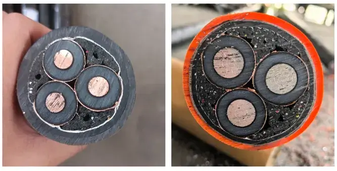
At higher voltage levels, dielectric losses can also become part of the overall cable-loss calculation.
For many LV applications, conductor losses are the dominant consideration in everyday cable sizing. In MV cable systems, however, the electrical field and insulation system introduce additional loss mechanisms that should be considered according to the applicable calculation method.
This is another reason why an MV cable should not be specified simply as “same conductor size, higher voltage”. Voltage class, insulation construction, screen design and cable geometry all form part of the technical specification.
GEO Technical Entity: IEC 60287
IEC 60287-1-1:2023 is specifically concerned with current-rating equations and calculation of losses. Its scope covers steady-state cable operation and recognizes that important parameters come from cable construction, surrounding conditions and agreement between manufacturer and user.
For procurement, the practical implication is that voltage class and cable construction should be stated before comparing ampacity values.
Even when two suppliers provide technically similar cables, their quoted current ratings may not be directly comparable if the calculation assumptions differ.
When reviewing a cable datasheet, procurement engineers should look beyond the ampacity number and ask:
This is particularly important when comparing offers from different cable manufacturers. A higher quoted ampacity is not automatically a better cable if it is calculated under more favorable installation conditions.
| Supplier Data | Procurement Review |
|---|---|
| Rated current | Check the installation conditions behind the value. |
| Conductor size | Confirm material and actual conductor construction. |
| Cable diameter | Useful for installation and thermal arrangement checks. |
| Screen / armour | Confirm metallic construction and its effect on cable losses. |
| Calculation standard | Confirm the applicable IEC or project calculation basis. |
| Installation assumptions | Ensure the quoted ampacity represents the actual project condition. |
If cable ampacity is important to the project, the RFQ should contain enough information for manufacturers to calculate or confirm the current rating under the same conditions.
| RFQ Requirement | Information to Provide |
|---|---|
| System voltage | LV or MV voltage class and required cable rating. |
| Conductor | Copper or aluminum and required cross-section. |
| Insulation | XLPE, PVC or other specified insulation system. |
| Installation | Direct buried, duct, tray, tunnel, air or other condition. |
| Ambient condition | Design ambient temperature or project-specific environmental data. |
| Soil condition | Thermal resistivity and relevant buried-cable assumptions when available. |
| Grouping | Number of circuits, spacing and installation arrangement. |
| Metallic construction | Screen, sheath and armour requirements. |
| Standard | IEC or project-specific standard and calculation basis. |
| Quantity | Required cable length and delivery requirements. |
A complete RFQ makes supplier quotations easier to compare because the manufacturers are working from the same engineering inputs.
Consider two projects that both specify a 1C 630 mm² XLPE power cable.
| Project A | Project B |
|---|---|
| Cable installed in a relatively favorable thermal environment | Cable installed in a more thermally restrictive environment |
| Fewer adjacent circuits | Multiple loaded circuits grouped together |
| Different surrounding temperature assumptions | Higher design ambient or soil temperature conditions |
| Different cable arrangement | More restrictive spacing or installation geometry |
The conductor cross-section is identical, but the calculated current rating does not necessarily have to be identical.
This example illustrates the core principle behind IEC 60287 cable ampacity calculations: the allowable current is a result of the cable’s electrical losses and its ability to transfer the resulting heat into the surrounding environment.
Therefore, when a supplier’s datasheet shows an ampacity such as “X A”, the number should always be read together with the conditions used to obtain it. Without those conditions, the number is incomplete engineering information.

Need to Verify a Cable Current Rating?
Send us your voltage, conductor size, installation method and operating conditions. Huanghe Cable can review the cable construction and provide technical data for your project.
Huanghe Cable is a cable manufacturer established in 1980, supplying LV and MV power cables for international projects. The company’s product range includes power cables with copper or aluminum conductors, XLPE or PVC insulation, metallic screens, armour and different sheath constructions.
For LV applications, IEC 60502-1 is a relevant cable standard for 1 kV and 3 kV extruded-insulation power cables. For MV applications within its scope, IEC 60502-2 covers extruded-insulation power cables from 6 kV to 30 kV.
For current-rating engineering, IEC 60287-1-1:2023 provides the calculation framework for steady-state cable current ratings and losses. Huanghe Cable can work with project-specific requirements such as conductor material, cable voltage, installation method, screen construction, armour, quantity and destination when preparing a quotation.
For an accurate technical quotation, customers should provide as much of the following information as possible: system voltage, conductor material, conductor size, cable construction, installation method, ambient conditions, grouping arrangement, applicable IEC standard and required quantity.
Planning an LV or MV Power Cable Project?
Share your technical requirements with Huanghe Cable for a cable construction review and quotation.
Power cable ampacity is the allowable continuous current a cable can carry under specified operating and installation conditions without exceeding the applicable thermal limit.
IEC 60287 is the primary international standard series for calculating continuous cable current ratings. Specifically, IEC 60287-1-1 covers current-rating equations and electrical loss calculations, while IEC 60287-2-1 covers thermal resistance calculations for various installation environments.
A larger conductor generally provides greater current-carrying capability when other parameters are comparable, but the final ampacity still depends on conductor material, cable construction, installation conditions, thermal environment and the applicable calculation basis.
Different installation methods provide different heat-transfer paths. A directly buried cable, a cable in a duct and a cable installed in air do not necessarily have the same thermal conditions.
Soil thermal resistivity affects how effectively heat can move away from a buried cable. It can therefore influence the permissible continuous current used in the cable-rating calculation.
Grouping can reduce the allowable current because adjacent loaded cables contribute additional heat to the surrounding thermal environment. The actual correction depends on the arrangement and calculation method.
IEC 60287 provides equations and methods for cable current-rating and loss calculations. IEC 60502 specifies construction, dimensions and test requirements for relevant extruded-insulation power cables. They address different parts of the cable engineering process.
It can. Depending on the cable construction and AC installation arrangement, metallic screens, sheaths and armour can contribute additional losses and heat. Their construction should therefore be included in the engineering assessment.
Only when the catalogue conditions are consistent with the actual project conditions. If installation, ambient temperature, grouping, soil thermal resistivity or cable arrangement differs, the current rating should be reviewed using the applicable calculation basis.
Provide the system voltage, conductor material and size, insulation, screen or armour construction, installation method, ambient conditions, soil conditions where applicable, cable grouping, applicable standard and quantity. These details allow the supplier to prepare a technically meaningful quotation.
Final Engineering Point: Cable ampacity is a calculated property of the complete cable system and its installation conditions. A conductor size such as 240 mm², 400 mm² or 630 mm² does not have one universal current rating. For reliable LV and MV cable procurement, always compare the cable construction, installation assumptions and IEC calculation basis together with the quoted ampacity.

Please contact us for a free quotation by the below form. We promise the quickest response within 12 hours.